
If you want big power from your tuned engine you need forced induction and turbos rule the roost when it comes to big boost. Here’s our complete turbocharger guide to help you understand how they work and how you can boost power.
What is a turbocharger and how do turbos work?
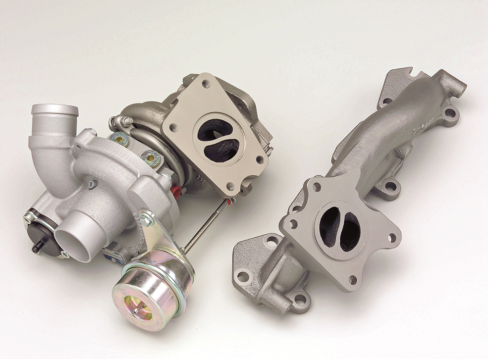
The turbocharger is essentially a centrifugal compressor. It’s almost identical to a centrifugal supercharger. However, instead of being driven mechanically from the engine, usually by a belt, it uses the exhaust gas energy travelling out of the cylinder head, through the exhaust manifold, to drive a turbine directly connected to the shaft of the compressor.
It has been said that this is ‘free’ energy and that the turbocharger does not take any power from the engine to drive it. However, this is not an accurate statement. The turbine is effectively an exhaust restriction. It slows the exhaust flow by using the kinetic energy of the gas to drive the turbine. The larger the exhaust turbine, the less restrictive it becomes. But, it also gets heavier and takes more energy to get it to accelerate (spool-up).
A smaller turbine will have less mass, and accelerate faster. However, it will eventually become more and more restrictive. Limiting the available top-end rpm flow and power. As we will discuss, this has a major effect on the suitability of any specific turbocharger against the intended use of the vehicle.
Who founded the turbocharger?
All hail the great man Alfred Büchi who invented the turbocharger and received a patent for his efforts in 1905. Aircraft development made use of the technology way before it hit the automotive market. The first to use it in a production car were General Motors in 1962. While Porsche made turbos sexy by creating the now legendary 911 turbo in 1974. Turbos are now used widely in both tuning and economy vehicles.
What turbo should I buy?
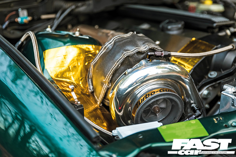
So, how do we select the correct turbocharger for our application? Well, we need to consider several factors. The selection of the compressor, the turbine and how we are going to use the vehicle. Getting these factors wrong can make the car a complete disappointment with dreadful turbo lag and a very narrow, extremely peaky powerband. We also need to consider shielding nearby components from the glowing red-hot turbine housing(s). As well as managing an appropriate oil supply to and drain from the turbocharger. We also need to fabricate an exhaust manifold to mount the turbo. As well as an exhaust system of the appropriate size to remove the expelled exhaust gasses from the turbo. This is generally much larger in diameter than the original exhaust.
As with any centrifugal compressor, we need to examine the compressor maps for the correct selection of the compressor wheel. We also need to calculate the airflow requirements of the engine. We can then plot this requirement on our compressor maps to find the most suitable compressor wheel that will operate in its highest efficiency island to reduce excessive charge temperature increases.
Turbo lag
Turbo lag is the biggest bugbear of the turbocharged car. It occurs where the throttle is opened, and there is a delay before there is any response from the turbo. Causes include using a turbine that is too large or an excessive turbine housing A/R (Area to Radius) ratio.
We then need to try and select the correct turbine wheel and housing for our engine. The turbine needs to be large enough to flow a large volume of exhaust gas without causing any significant restriction at peak rpm. This tends to lead towards a turbine that will be very heavy, requiring large exhaust flow to get it spinning fast enough to produce boost. However, this also has the downside of meaning this install may well be almost halfway up the rev range with absolutely no low rpm boost and dreadful turbo lag.
Smaller turbo turbine
If we decide to opt for a much smaller turbine wheel, then it will spool up to speed, as much as 200,000rpm, much faster. This enables boost from much lower engine speeds, but can then effectively block the exhaust at high rpm. In turn, this limits power production and increases fuel consumption. Therefore, we need to select a turbine somewhere in between the two so that, on a performance road car, we start to build boost around one-third of the maximum rpm of the engine and continue to do so up to the redline.
We then need to consider the turbine A/R ratio we require for our selected turbine. The A/R ratio is the ratio of A (Area of the turbine housing inlet) to R (Radius of the center of the turbine to the middle diameter of the turbine inlet). A small A/R ratio will give better low-speed boost whereas the higher A/R will flow better at high rpm. It is this combination where road car manufacturers tend to choose mid-range power and a conservative turbine/housing selection rather than an all-out power combination.
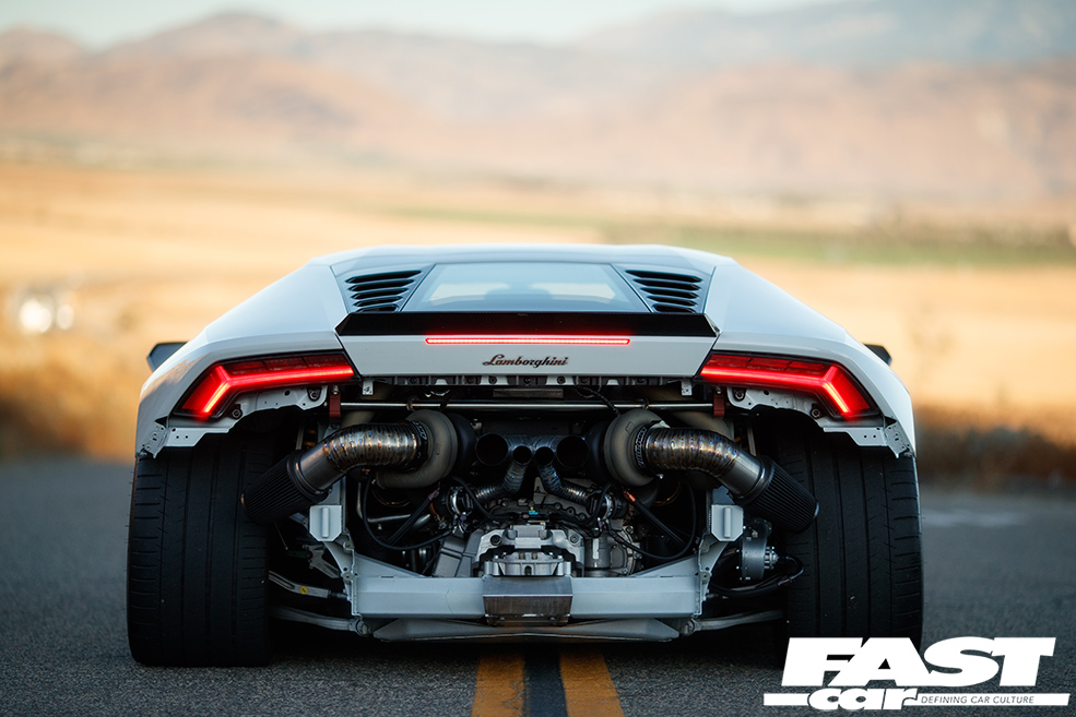
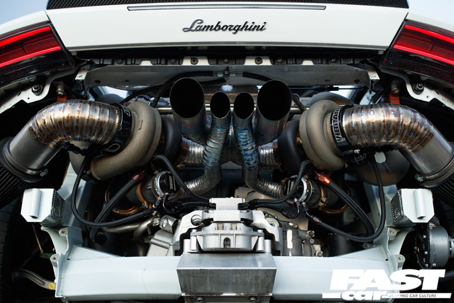
Twin turbos and more!
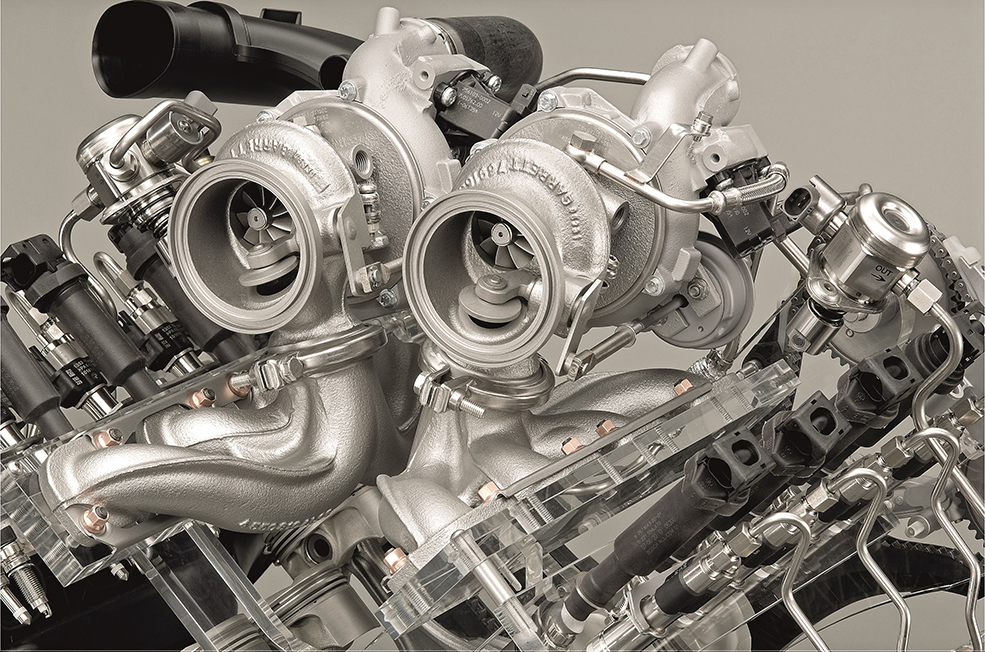
There are however ways of having your cake and eating it, and that is with the use of multiple turbochargers. The use of more than one turbocharger can give the advantages of both a single large and a single small turbo. The inertia of the multiple small turbine wheels, combined with the pulsing flow of a reduced cylinder count to each turbine, means early boost production, and the additional flow capacity of them combined means less or no restriction at high rpm. When we get to larger V engines, eight, 10 or 12 cylinders, then twin, identical turbos, one on each bank, is the preferred combination whereas on smaller in-line engines a single turbo makes the installation far more practical with little requirement for
multiple turbos.
Sequential Turbos
You also have sequential turbos, something which only BMW’s multi-turbo diesel engines utilize. The basic principle is that you have a small turbo that spools up quickly to deliver good low-end response and performance and a second larger turbo that takes over at higher rpm. On the M57 engine, BMW actually put the large turbo first in the setup, so air was already flowing through it to reach the small turbo and this was done so that the transition from small turbo to big turbo was much smoother. On the triple-turbo N57 in the M50d models, a small turbo operates at low revs, with a large turbo joining in the mid-range and then, finally, the second small turbo comes online at higher revs with all three working together, while the B57 uses an even more complicated quad turbo setup.
Another sequential turbo system we should mention is where we direct all the output from one compressor into the intake of the second compressor, known as compound turbocharging. While only really seen in racing, this can produce enormous levels of boost: consider that a single turbo can only produce around a 3:1 pressure ratio, so, let’s say three times atmospheric pressure or 3 bar (45 psi) of boost. If we now feed the second turbo with this 3 bar air pressure, and it then further adds a 3:1 pressure ratio, we can achieve around 105 psi boost!
What are twin-scroll turbos and how do they work?
Turbochargers respond better to a pulsed exhaust input. This is where twin-scroll (BMW, for example, calls it TwinPower) housings and manifolds come in, which keep exhaust gasses from multiple cylinders separate from each other, retaining the pulsed exhaust input.
The exhaust streams from the cylinders group together in such a way that ensures the turbo receives these pulsed inputs. Twin-scroll setups offer quicker boost response, improve low-end performance and reduce fuel consumption, so you can see why manufacturers use twin-scroll setups in single-turbo applications.
Turbo Technology
There have been other developments in turbocharger design in an attempt to reduce the spool-up time and hence lag with the use of ceramic bearings instead of the more usual oil-filled plain bearing bushes, and of ceramic, lightweight turbine wheels. Proven to decrease inertia by up to 40%, reducing lag by around 30%, they are more fragile, allowing only around 1 bar boost before mechanical failure of the material occurs, although this is easily enough for most road applications.
Another successful design for anti-lag has been the adoption of VGT (Variable Geometry Turbochargers), VAT (Variable Area Turbines) and VNT (Variable Nozzle Turbines), where the actual geometry of the turbine alters in use to change the effective way in which the turbine reacts. The Garrett VNT system uses multiple moving vanes in the turbine housing that, at low rpm, direct the exhaust to flow through a smaller passage to rapidly accelerate the turbine wheel to make it act like a small housing, but then with the vanes gradually opening as rpm rises to minimize exhaust flow restriction. These VNT turbos can reduce spool-up time by around half that of a similar-sized non-VNT unit.
Twin-scroll swing flap turbocharger
Another development is the twin-scroll swing flap turbocharger where a plate directs flow into a small A/R scroll at low rpm for faster spooling of the turbo, then opening a larger A/R scroll for higher rpm, or the alternative arrangement is a flap that blocks the flow from the secondary scroll to the turbine and then gradually opens it into the twin-scroll operation position. The VAT turbocharger from Garrett was another design, this time altering the area of the turbine inlet, reducing the area to increase the speed as it hits the turbine, accelerating it faster, then gradually opening as speed increases to increase flow.
What does a wastegate do?
A wastegate controls boost by allowing exhaust gasses to bypass the turbine once the required boost pressure has been reached in order to maintain the desired level of boost. Let’s get one thing out of the way – wastegates don’t actually make any noise, there’s no such thing as wastegate chatter, a wastegate is literally a flap that opens to vent exhaust gasses, that’s it. If it’s making any sort of noise, like the old N54 turbo rattling wastegate problem, that’s not a good thing. An actuator controls the wastage which physically opens the flap. There are mechanical ones which measure boost pressure directly from the turbo and, once the desired pressure has been reached, the air pressure itself forces the actuator to open the flap, and the more pressure there is the more the flap opens in order to regulate the boost pressure.
Electric wastegates
Electronic ones, meanwhile, use a sensor to read the boost pressure and this then sends a signal to the wastegate actuator when it’s time to open the wastegate. On some setups the wastegate is actually normally open and only closes once it receives a signal from the vacuum pump to close it and allow the turbo to spool, but the basic principle is the same and it functions in the same way as a more traditional wastegate setup once the desired boost pressure has been achieved. Boost controllers, meanwhile, raise boost levels by modifying the amount of pressure that the actuator ‘sees’ before it opens, allowing the turbo itself to generate higher levels of boost before the wastegate regulates it, but they can’t raise boost pressure beyond the specific maximum that a turbo is able to generate.
Internal wastegates
Internal wastegates feature on most factory turbo setups, this houses the wastegate inside of the turbo exhaust housing. An external wastegate is a separate item mounted to the turbo. This is what most aftermarket turbos look like. The downside of internal wastegates is that the exhaust gasses dump into the path of the exhaust gasses coming out of the turbine and this disrupts the flow, causing turbulence and back pressure, which is bad when you’re going for power.
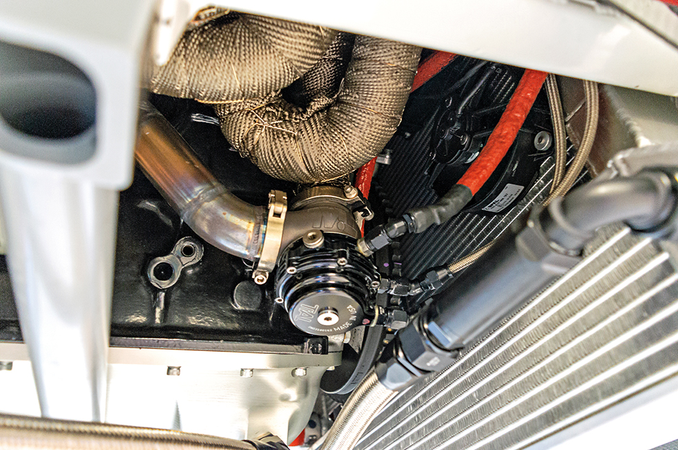
External wastegates
With an external wastegate, you can have these gasses re-enter the exhaust at any point you want, minimizing turbulence and back pressure, or you can vent them directly to the atmosphere using a screamer pipe, so called for obvious reasons. External wastegates also make it easier to change the internal spring, allowing you to increase (or decrease) the amount of boost it can comfortably hold.
Check out our full guide to wastegates.
Blow-off valves
Blow-off valves, commonly referred to as dump valves, also known as diverter valves placed somewhere after the turbo and ahead of the throttle body and they give the compressed air somewhere to go when you come off the accelerator and the throttle shuts. When the turbo is no longer under load it is still spinning. The turbo chops up the air backed up against the throttle plate and you get a fluttering sound (compressor surge).
A blow-off valve is held closed while you’re accelerating and when you let off the throttle it opens and allows the air to escape – an atmospheric blow-off valve will make the various chirping, chuffing and sneezing noises associated with turbocharged cars, while a recirculating one doesn’t, simply recirculating the excess air until the throttle is opened again, the valve closes and the air can now pass through the throttle body and enter the intake manifold once more.
If your engine uses a MAF then you shouldn’t use an atmospheric blow-off valve as air that your MAF has already accounted for will vent to atmosphere and your engine will end up running rich, but if your engine uses MAP (manifold absolute pressure) then the sensor measures air pressure at the intake manifold so venting before this won’t cause any problems.
Check out our guide to blow-off valves.
Turbocharger guide first appeared in Performance BMW magazine. Words: Gerry Speechley, Elizabeth de Latour Photos: Viktor Benyi, Patrik Karlsson, BMW.